We
are developing a new technique for low noise sub-millimeter
to mid-infrared sensing using a cryogenic bolometric detector
as an active element in a tuned quasi-optical resonant
interference filter. All filter and bolometer components
are assembled from micromachined silicon structures. The
absorption, transmission, and reflection characteristics
of the detector depend on frequency in a controlled manner:
a Frequency Selective Bolometer (FSB).
A
set of FSBs will be cascaded within a straight light-guide
to produce a high-efficiency, compact, multi-band radiometer.
Instruments based on FSB technology will have important
advantages over current multi-channel bolometric radiometers,
including: 1) the expected coupling efficiency is several
times higher than traditional multi-channel bolometer
systems, significantly improving detector sensitivity;
2) the cryogenic optics are smaller and more compact,
reducing
the demands on cryostat size and weight; and 3) there
is no restriction on the geometry in the focal plane.
An FSB system is amenable to configuration as a close
packed focal-plane array, permitting efficient use of
the throughput of a telescope. These advantages are key
for future sub-orbital, and space-based astrophysics and
space-physics experiments.
In
the near future, we plan to extend this design for use
in the mid-infrared where compact, multi-frequency, high
efficiency radiometers are important for airborne measurements.
Advantages
of FSBs
Traditionally,
multi-mode bolometric radiometers have used spectral filters
to define the band of sensitivity and a broadband absorber,
sometimes matched with a tuned backshort. A number of
such filters can be combined with several detectors to
provide a multi-band dichroic system.
Alternatives
to this type of system is either a filter wheel approach
which requires sequential measurements to obtain spectral
information, or a focal plane with different pixels having
different spectral response.
The
FSB system overcomes the limitations of these systems.
Because it permits the possibility of cascading multiple
FSBs within a straight light-pipe it enables a complete
multi-channel radiometer in a single compact cylinder.
Arrays of such cylinders allow greater freedom in the
geometry of the focal plane. Because of the small size
of the FSB radiometer, the cryogenic system can
be
simplified. This has important benefits for space, airborne,
and balloon-borne applications.
Figures
and Tables

Figure
1. Schematic of a Frequency Selective Bolometer
(FSB) Radiometer with eight frequency bands. The radiation
enters the feed horn on the left. After passing through
the étendu (0.15 cm2 sr)
defining aperture, the beam is expanded and passes through
the FSB elements. Because each element absorbs only
in a narrow range of frequencies, they can be cascaded.
To avoid frequencies in the diffractive region of a
given filter, the elements are arranged from highest
to lowest frequency. Between FSBs, a high frequency
absorber such as Fluorogold of the appropriate thickness
reduces radiation above the design frequency. This example
of an FSB radiometer, which we propose to construct
and characterize is designed for the sub-millimeter.
A similar, smaller device will be designed for use in
the mid-infrared.

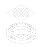
Figure
2.
Drawing of a mesh on the silicon grid and the FSB
mount. The mesh has a silicon frame by which the silicon
grid is supported. The resonant metal mesh is in the
silicon but is not visible in this drawing. The bolometer
element will look identical to the meshes but the metalization
thickness will be optimized for maximum absorption in
band. The Invar mount is shown below the mesh for clarity.
The holes in the mount are used to feed the leads from
the up-stream FSB elements to the back.
Figure
3. Comparison of analytic prediction and measurement
of the transmission of a mesh of crosses on a silicon
grid as shown in Fig. 2. In this case, the metalization
has high conductivity and no losses. The measurement
is made with an FTS interferometer with an étendu
of 0.5 cm2 sr on a full sized 1 cm diameter
mesh. Detector noise causes the wiggles on the measurement
line. An empirical shift of 15% due to the effects
of the dielectric constant of the silicon grid has
been fit in the mesh model.

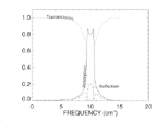
Figure
4. Modeled performance
of an FSB element. The curves show the transmission,
reflection, and absorption for the FSB versus frequency
for a device tuned to o = 10 cm-1. High efficiency
is possible for both absorption and transmission.

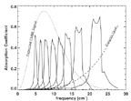
Figure
5. The model of the absolute absorption coefficient
of an eight-band FSB system as a function of frequency.
The detector geometry would be a small tube like that
shown in Fig. 1. The calculations include the bolometer
coupling efficiency and the losses in the high-frequency
absorber material. Efficiency of typical dichroic,
multi-spectral bolometers systems is less than 10%.
These curves can be used to calculate the sensitivity
of the system to a given signal. An example of such
a calculation is shown in Table 1.
For
the complete paper please see: fsb-kowitt.pdf
For
a pdf version of this document please see
meyer.pdf