· Mint
· Backend
» Channelizer
· Design
· Performance
· Future Revisions
· Correlator
The Channelizer is the first component of the Backend for MINT. The IF from each of the 4 mint receivers ranges from 4 to 6 GHz. The digitizers, however, can only sample at 1 GHz, which implies a 500 Mhz Nyquist frequency.The job of the channelizer is to split the IF signal into four 500Mhz bands,then downconvert each band to baseband. The MINT design aims to achieve simplicity and stability at low cost.
General design:

fig1. PDF of fig. 1
The frequency splitting is accomplished using a 4-way power splitter
followed by bandpass filters tuned to select the separate bands. The
bandpass filters are followed by mixers, whose LO ports are fed by 2 LO's. The LO's
can be shared by adjacent bands if one mixer is used in Upper SideBand
and the other is used in Lower SindBand. The mixers are followed by amplifiers
to bring the signal level to a value tolerated by the digitizer.
Integrated approach:
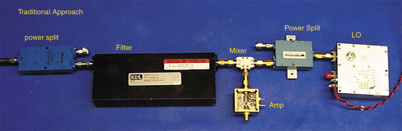
fig 2. adobe illustrator 8.0
The traditional approach to building his type of device is to buy all of the components separately and connect using SMA barrels. As you can imagine, this is the cost-inefective appraoch. It also involves many connectors, each with a high failure rate.
The alternative is to construct an integrated microwave circuit. Microwave circuit boards have many of the same advantages of integrated electronic circuit boards like smaller size and high reproducability. Micowave circuits have added benifit that many microwave components can be constucted into the cuircuit board itself. The MINT channelizer incorporated both the power splitters and the bandpass filters into the layout of the circuit board. In addition, the mixers and the amplifiers come in small surface mount packages, which allows for a truely connectorless design.
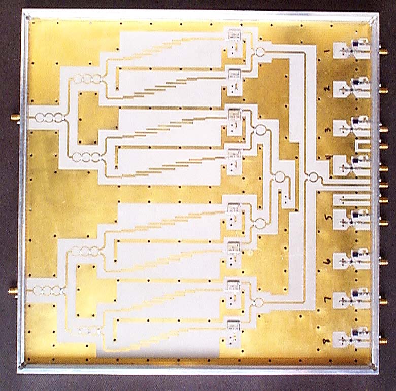
fig 3
The actual MINT channelizer is shown above. The board size is 13.1"x13.1".Two full channelizers fit on one board. Signals enter from the left side, and leave on the right. LO signal is sent in on the right, and split between the mixers
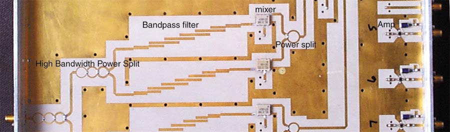
fig 4
In this blown up view, we can see the components in greater detail.
After the IF port on the mixer, the signals traverse a short distance on
the top layer before sinking through the board an under the LO lines and
reemerge at the far right hand side before entering the amplifier.