Oxford Experimental Radio/mm Cosmology

Clover Instrument
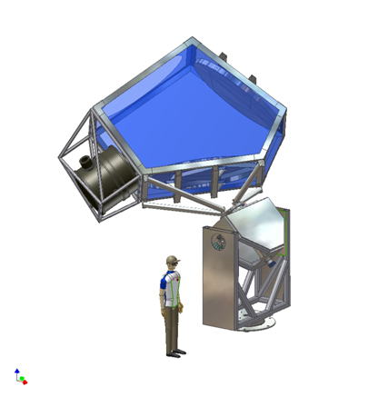
- The CLOVER Instrument is based upon an off-axis telescope.
- The optics will be of the CRA (Compact Range Antennas) type, their size scaling down with the wavelength i.e. one at 97 GHz (the "Low Frequency Instrument" and a combined 150/220 GHz Instrument (the "High Frequency Instrument").
- Each telescope features a 3-axis steerable polarization over altitude over azimuth mount.
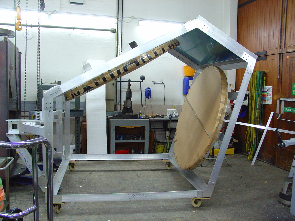
- Each optical assembly (OA - the structure mounted on top of the mount) will include a frame supporting a cryogenic receiver, a star tracker, the receiver electronic boxes and a co-moving ground shield used to block polarized spillover.
|
Specifications of Clover
|
| Band Center (GHz)
| 97, 150, 225
|
| Number of Single Polization Detectors |
192, 200, 200 |
| NET (µK sec) |
164, 254, 664 |
| Beam FWHM [arcmin] |
7.5, 5.5, 5.5 |
| Sky Coverage [deg2] |
1000 |
| / Range |
20 to 1000 |
| Operation Time [years] |
2 |
| Integration Time [years] |
0.8 |
| T Sensitivity per 8' pixel [µK] |
0.8 |
| Q Senistivity per 8' pixel [µK] |
1.1 |
| Minimum r |
0.03 |
Telescope and Optics
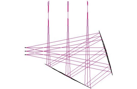
Each Clover telescope consists of a Compact Range Antenna feeding 100-200 (depending on frequency) dual polarisation receivers. The optics for each telescope are scaled, so that all frequencies and pixels have well matched beams (~5'-8' wide). Each telescope will be mounted on its own 3 axis mount (alt over az, with rotation about the optic axis to eliminate telescope polarisation effects).
Receivers
The focal plane of each telescope is made up of a large number of phase-moulated dual-polarisation receivers. The two polarisation signals entering each receiver are phase modulated by a rotating metal mesh waveplate, and differenced to allow near instantaneous measurements of the I, Q and U Stoke's parameters.

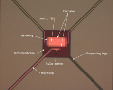
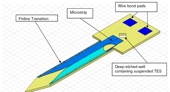
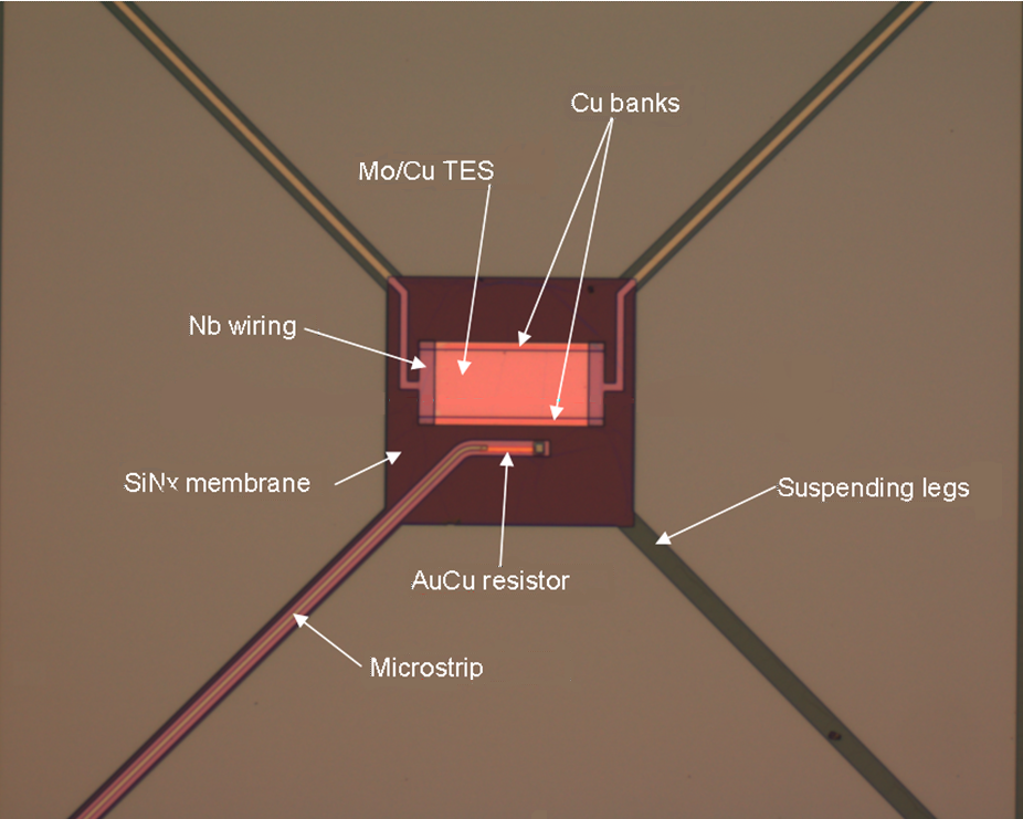
The Clover detectors are MoCu transition edge sensors (TES) fed by finline waveguide-to-microstrip transitions (at 97 GHz) and rectangular probe OMTs (at 150 and 220 GHz). The detectors will operate at a temperature of 100 mK, and will be read out by time division multiplexed SQUID amplifiers.
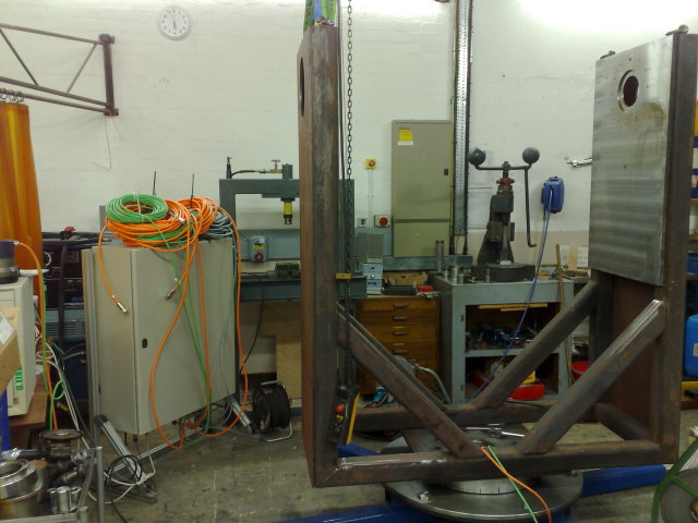
The LF mount has now moved under its own power and both optical assembly frames are complete
Observing and Data Analysis
Observation Strategy
Clover will spend 2 years (~1 year observing time) observing several patches of sky. These fields will be chosen to have the lowest possible foreground emission, and to give a total area of ~1000 square degrees. Each field needs to be large enough to allow the low end of Clover's angular scale coverage to be reached.
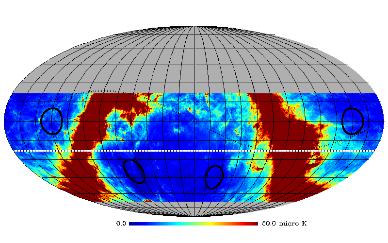
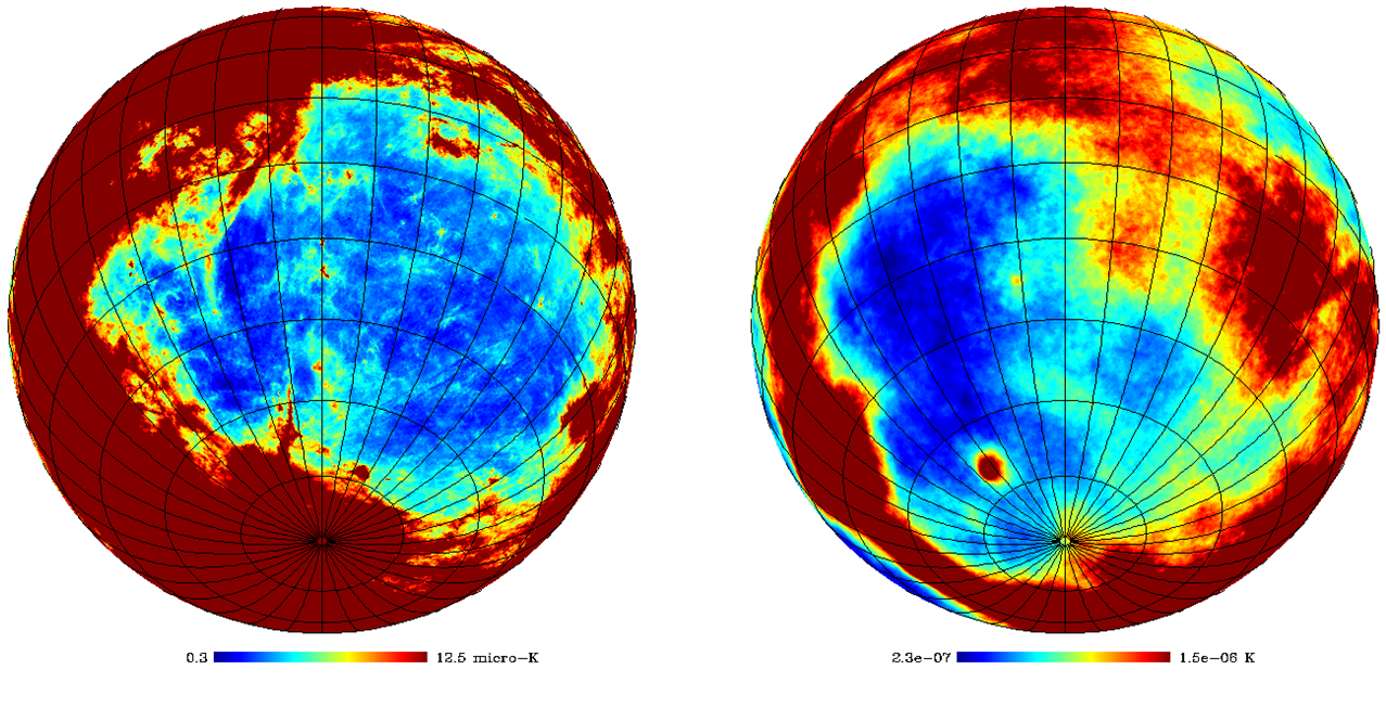
Foreground Removal

The dominant polarised diffuse foregrounds at the Clover frequencies are synchrotron emission and thermal dust emission. Models show that the dust is dominant at all three frequencies, though synchrotron is important at 97 GHz. Removal techniques, such as Internal Linear Combination (ILC), can reduce the foregrounds down to as low as ~0.01 micro K, compared with a B-mode signal of around 1 microK (for r=0.01).
Clover is in an advanced state of construction, with both telescope mounts and optics being assembled in Oxford, both receivers and cryogenic systems being assembled and tested in Cardiff, the 97 GHz feed horns and OMTs delivered and undergoing testing in Manchester, and science grade detector fabrication underway in Cambridge.
March 2009

The LF telescope mount and optical assembly have now been moved to the AIV area in the covered yard at Oxford where the assembly and testing of the Clover LF instrument will take place

Fabrication of the struts joining the optical assemblies to the telescope mounts is now underway
Jan 2009
The assembly of the second mount has started in the Oxford workshop high bay
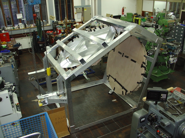
Both sets of mirrors have been test fitted to the Optical Assembly frames to check the alignment mechanisms.
March 2009
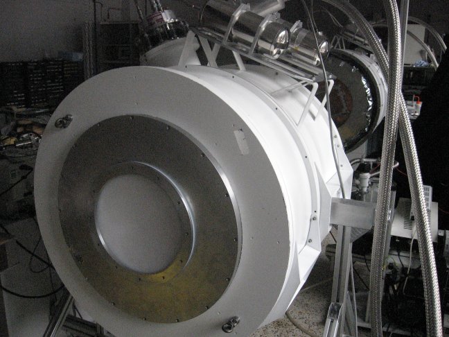
The HF instrument cryostat is now cold and undergoing optical load tests in Cardiff

The LF instrument cryogenics are being integrated into the LF cryostat in Cardiff
|