Main
· Science
· Instrument
· Backend
· Channelizer
· Correlator
· Design
· Signal Integrity
» RF components
· A/D converter
· Deserializer
· Correlator
· Enclosure
· Fabrication
· Performance
· Receiver
· Optics
· Data Aquisition
· Local Oscillator
· Base
· Site
· Analysis
· Results
· Publications
· Team
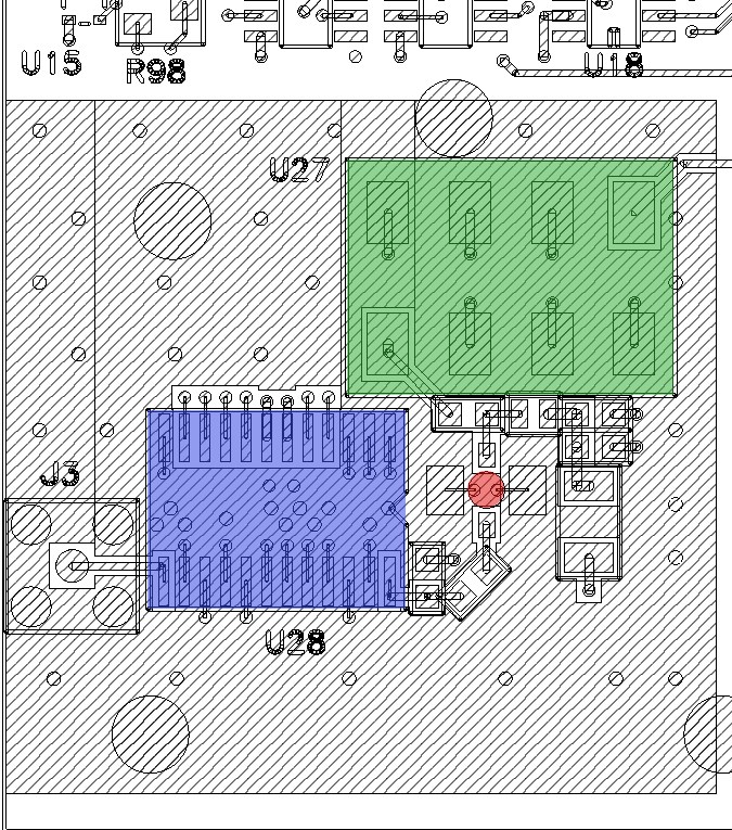
Digitizer RF components
The signal to each of the four digitizers enters by an SMA jack on the left of the board. The signal follows 50 ohm traces to a digitally programmed attenuator (at20-0107)(blue in fig below) then to an RF amp (sga-6486) (red) and finally to a low-pass filter (sclf-550) (green) with cutoff of 20 dB at 550 MHz. The attenuators are programmed by lines from the system controller fpga. In this section of the card all traces run along the top side of the card which is plated with analog ground.