Main
· Science
· Instrument
· Backend
· Channelizer
· Design
· Software
· Transmission line
· Power Splitter
· Bandpass Filter
· Mixer
· Amplifier
» Jumper
· SMA Connector
· Enclosure
· Fabrication
· Performance
· Future Revisions
· Correlator
· Receiver
· Optics
· Data Acquisition
· Local Oscillator
· Base
· Analysis
· Results
· Publications
· Team
Because we decided to put power splitters on the output side of the channelizer, we needed a way to cross signals. There are a number of ways of doing this, and we investigated many of them. The easiest method is to jump on signal over the other with a wire jumper. We wanted to avoid the impedance jump and the phase variability of this method. All of the other options available at the time involved vias. The next easiest possibility is to make the dielectric substrate 2 -layered, then run one of the signals below the other. This method induces ~ -18dB coupling between the signals. More importantly though, it induces a slight phase shift in the high frequency signal. The way to completely isolate the two signals is to place a ground plane between the two transmission lines. This is generally how electronics manufacturers do it. We wanted to avoid this, however, because it was unclear how our circuit would perform with the ground plane separated from the case.
The way to solve this was to make a small "jumper" which would span the short distance that it would take to cross lines. The jumper is a 3-layer circuit. Because it has ground plane on either side, it is a stripline instead of microstrip circuit. This, of course, means that the design equations are different from microstrip circuits. Stripline circuits are in general thinner than microstrip circuits. See Pozar for more details.
At either end of the jumper, there are "blind" vias to the transmission line as well as through-pads on the ground layer.Blind vias are vias that do not extend through the entire board and are generally more expensive that through vias. The idea is that we would laminate the jumpers on the underside of the channelizer. Because we were going to do this by hand, we needed a way to align the laminates. That is why there are holes at the end of the circuits. The lamination process would involve inserting pins through the holes during mounting.
The jumper is also "edge plated", which ensures that the ground connection is sold around the perimeter of the device. There is also oval shapes cut from the edge to improve the ground area.
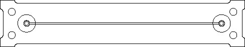
fig 1 Artwork for the jumper. P3layer.dxf
P3layer.dwg
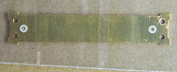
fig 2 One of the fabricated jumpers.