Main
· Science
· Instrument
· Backend
· Channelizer
· Design
· Software
· Transmission line
· Power Splitter
· Bandpass Filter
» Mixer
· Amplifier
· Jumper
· SMA Connector
· Enclosure
· Fabrication
· Performance
· Future Revisions
· Correlator
· Receiver
· Optics
· Data Acquisition
· Local Oscillator
· Base
· Site
· Analysis
· Results
· Publications
· Team
The mixer does the conversion from the IF band to a secondary IF band, which is baseband (beginning at 0 Hz) in the case of a digital correlator. Because of the specific arrangement of our bands, we could use 2 lo's to mix down 4 different bands. 2 bands are mixed in USB and the other 2 are LSB. In prototyping, we tried 2 different types of mixers, open carrier and surface mount. Open Carrier mixers are higher performance, so we tried them first. The problem with open carrier mixers is the mounting method. The best way to mount this type of mixer is to cut out the right shape in the substrate then fit the carrier into the slot. The connections to the signal traces should be made by wire bonding. We tried 3 brands of mixers, all of them had matching problems, either due to the connection method or due to internal mismatching. Surface mount mixers offered an easier connection method at the expense of slightly poorer performance.
The mixers we chose are the sky-60 series from Minicircuits. The RF range is 2.5-6 GHz, the IF range is 0-1500 MHz. The worst spec on the device is the LO-IF isolation, which is only 14dB typical and 8 dB min. So we expect lots of the LO getting through the IF port. What saves us is the bandpass of the channelizer and correlator amp, and the anti-alias filter on the correlator. These two effects combined should give another 40dB of suppression. Another problem with this mixer is the internal matching. See performance for a discussion of how this affects us. See Future Revisions for a new mixer that we would use today.
With a surface mount mixer, the only important thing is good layout. The sky-60 has 8 pins, 4 of which are ground. With most microwave devices, good grounding is crucial. There must be a low inductance path from the ground pins to case ground. That is the reason why the ground layout is a small sheet with many ground vias.
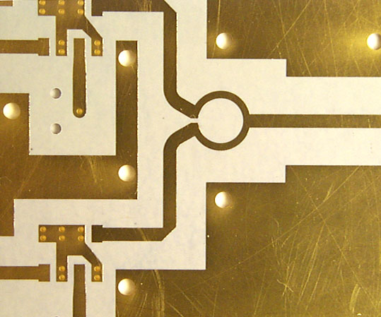
fig 1 The mixer layout before the mixer is mounted. Also shown the the power splitter that feeds the lo port on 2 mixers. The if port is connected to the trace coming extending to the side and into a via.
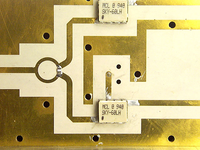
fig 2 The mounted mixers. The reason why the solder is dull is because it is indium based. We used indium solder for the lower melting temp.